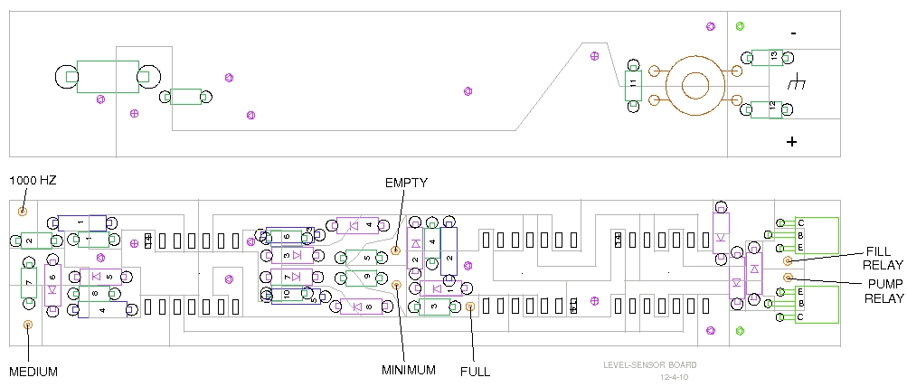
The first version of the sensor worked well, except for one annoying problem. The CMOS ICs would die after a few weeks or months.
I revised the circuit several times and added this to the website write-up:
"There are quite a few sources for spikes on the 125Vac line: pump moter, fill solenoid, everyday power variations. I recommend a transient suppressor diode to clamp the supply voltage at less than 18V. I used a 1.5KE13A in my control box because my transformer has slightly less than the normal 12.6V output. My transformer also had a fairly high internal resistance (8.2 ohms) so I used no series resistor in line with the TVS diode. If your transformer is a little beefier, I think a 10-ohm resistor should be added before the diode."
But the problem persisted, so I revised the circuit completely. I dropped the IC voltage to 5 volts to allow a lot of headroom between the operating voltage and the maximum IC voltage. I added a 5 volt regulator. I changed to a ground-referenced NPN-output configutation. These were shotgun measures as I didn't, and don't, see what was wrong with the original design.
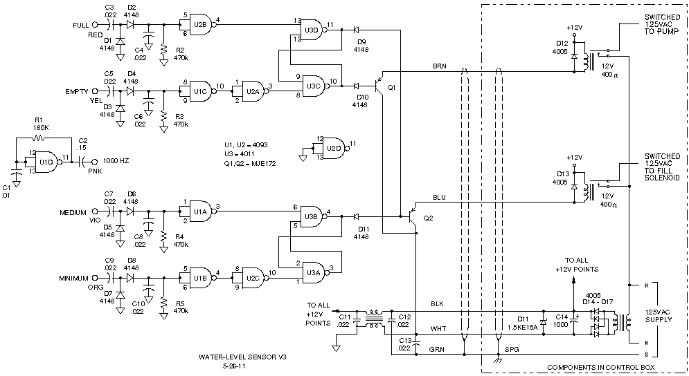
The information following is just a description of the circuit before it was redesigned.
Resistors R1 through R4 are sensitivity resistors and are shown as 470k, but will depend upon the screw size, the screw location, the conductivity of the water, and coupling between wires in the sensor pipe. I simulated this circuit with water at 20k wet and 200k dry, which gave voltages at the gate of 3.99 volts and 9.24 volts respectively with a 12-volt supply. The switch points of the 4093 are 3.96V and 9.24V worse case @25C. Adjust the resistor values to suit your conditions. You can adjust C2 to shift the trip point globally, within a small window. I suggest you keep C2 reasonably high, and R1 through R4 low, as reduction of the source oscillator voltage makes the detectors more suceptible to noise. I tested my values in a tub of water before I sealed the pipe. Tap water measured 10k at the ends of the wires before board connection. It was too difficult to measure the actual board voltage levels during the test in water.
There are quite a few sources for spikes on the 125Vac line: pump moter, fill solenoid, everyday power variations. I recommend a transient suppressor diode to clamp the supply voltage at less than 18V. I used a 1.5KE13A in my control box because my transformer has slightly less than the normal 12.6V output. My transformer also had a fairly high internal resistance (8.2 ohms) so I used no series resistor in line with the TVS diode. If your transformer is a little beefier, I think a 10-ohm resistor should be added before the diode.